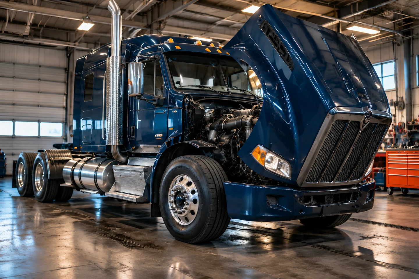
Continue training
Start here: Circuit 1
Learn to follow the power with a simulated meter. Try a short guided circuit.
Circuit 1 is ready · no signup to try.
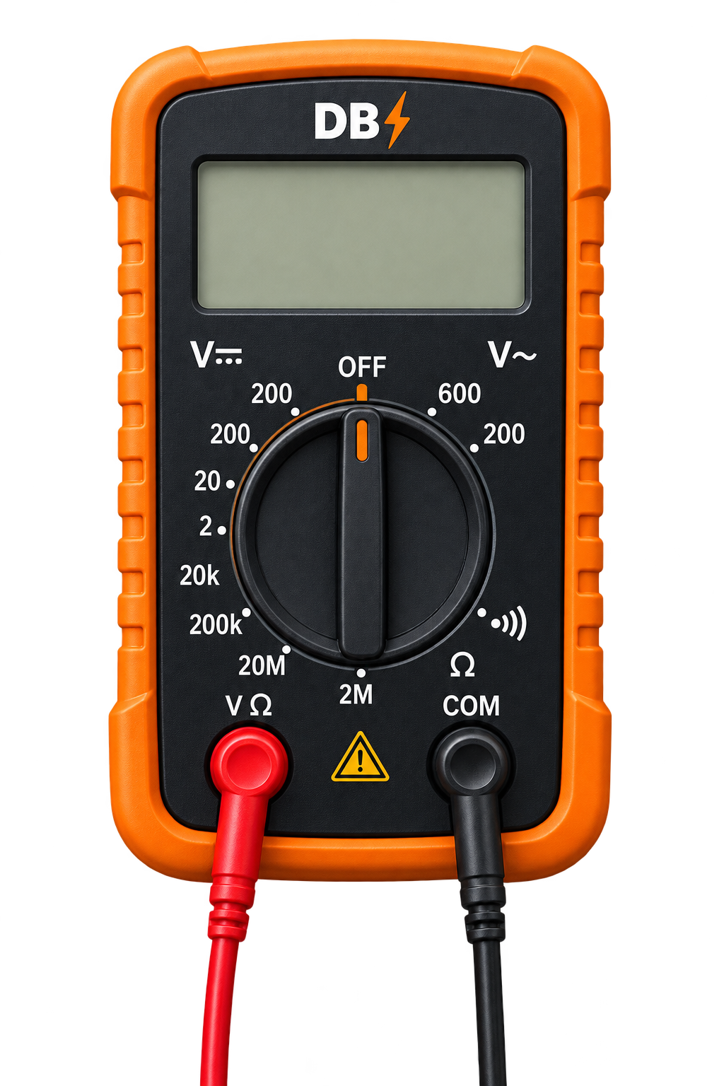
MEASURE. DIAGNOSE. VERIFY.
The training interface did not load completely. Check your connection and reload. Saved account progress stays on the server.
Opening your workshop…
Your next test starts here.
Continue training
Learn to follow the power with a simulated meter. Try a short guided circuit.
Circuit 1 is ready · no signup to try.
Truck powers up but won’t crank.
Complete your first diagnostic activity to see your strengths and next practice area.
Try a circuit, then save your progress with a free account.
Original generic training circuits. Educational values are not manufacturer specifications. DieselBench is independent and does not award a trade licence or government certification.
Sign in to save progressBuild confidence. Test your process.
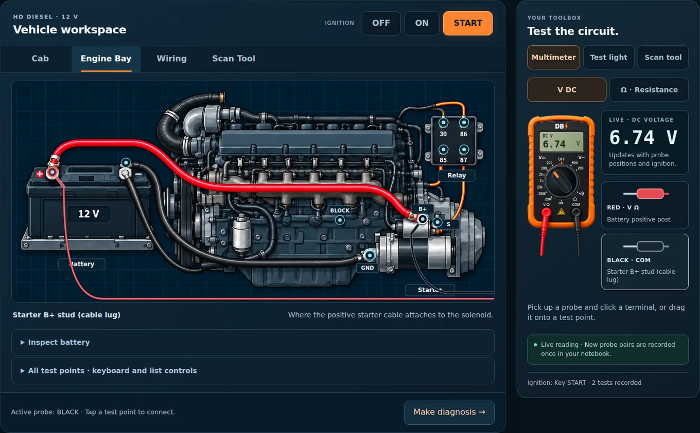
Battery, cables, relay or starter? Test the circuit and prove what failed.
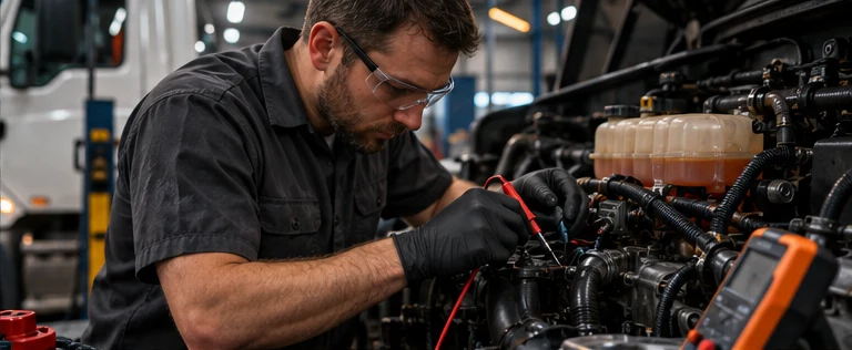
Read the complaint. Test, diagnose and verify a repair.
23 families · 74 fault variants · Saved diagnostic path
Independent trade exam practice.
Truck & Transport / Truck & Coach
Find your strengths and weak areas.
Six levels · Review answers after submissionIndependent training. Red Seal-style questions are not official exam content. Images are illustrative; use the diagrams and readings inside each activity for diagnosis.
Build the knowledge behind a confident diagnosis.
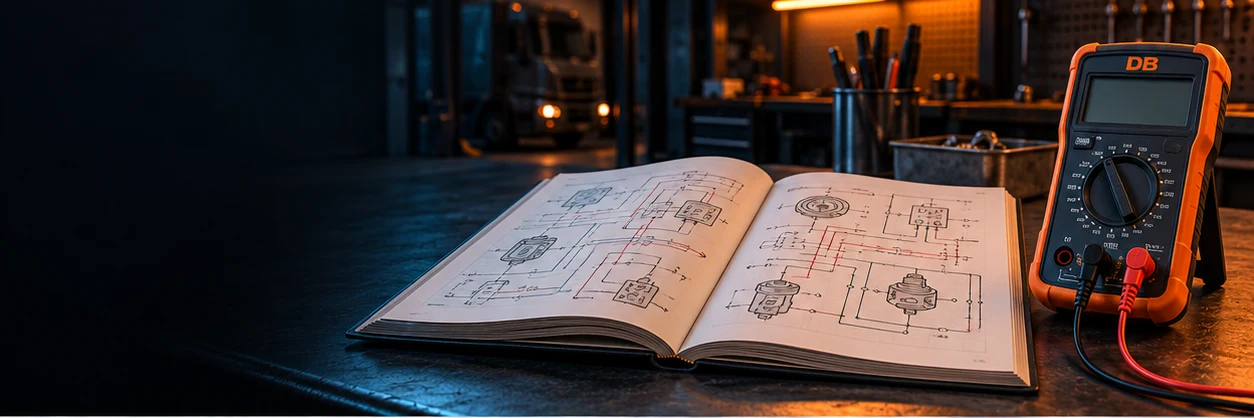
Explore electrical fundamentals, sensors, circuits and networks.
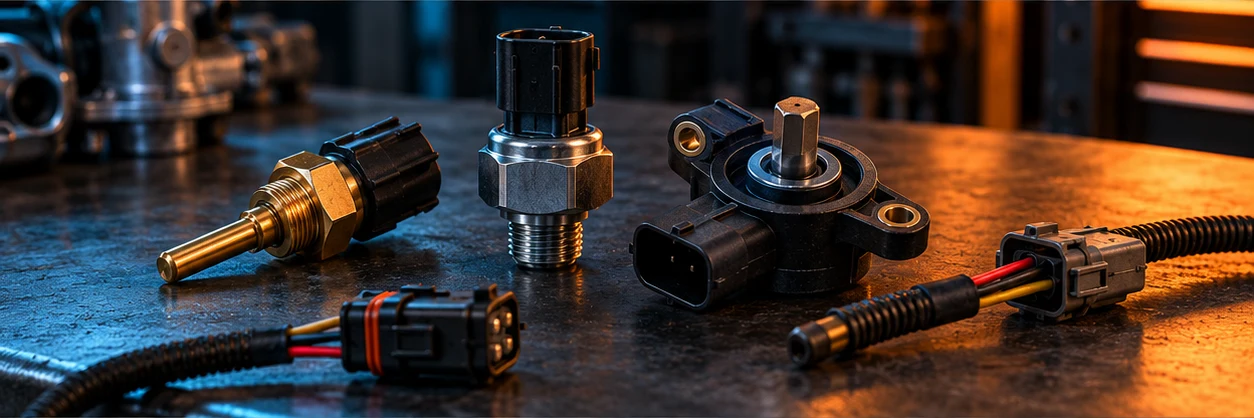
Understand sensor operation, wiring and signals.
WIRING · SIGNALS · IDENTIFICATION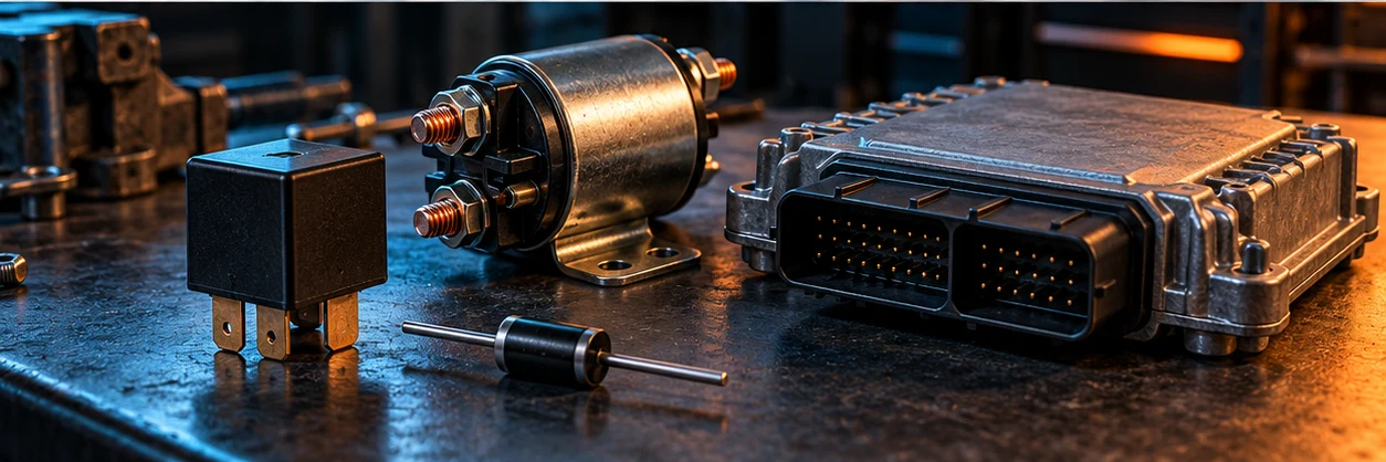
Learn how relays, solenoids and ECU drivers work.
RELAYS · DIODES · SOLENOIDSElectrical Essentials and Circuit Trainer are in Workshop.
Independent educational training. Images are illustrative; use the labelled diagrams and lesson explanations inside each activity. Refer to the correct service information when working on a vehicle.
Heavy-duty diesel · Dash is on, engine will not crank.
Read the complaint, recreate it, collect measurements, choose a repair and verify the original conditions.
Driver states
Everyone receives the same fault. One scored attempt per week. Ranking: five-star score plus useful-test percentage; earlier completion breaks ties.
These fictional jobs use conventional 12 V / 5 V teaching values. Scope traces are synthetic, with fixed signal/return connections named on each trace. They teach interpretation and do not decode real CAN messages. Use OEM wiring, sensor, timing, charging and test limits on a vehicle.
Isolate power before resistance tests. Use a rated clamp for current. Wet, hot and wiggle controls are simulated conditions; follow safe OEM procedures on an actual vehicle.
Your least-practised and lowest-rated areas appear first. Ratings describe your recorded exercises; they are not a trade qualification.
Confirm connector ID, pin number and whether the view is terminal side or harness side. Opposite views can mirror pin positions. A wire colour helps locate a circuit; it does not prove a pin’s function.
Use a proper backprobe adapter. Do not force a meter lead into a terminal or spread it. Inspect locks, seals, terminal tension and fretting; repair using the specified terminal and crimp tool.
Black lead in COM, red lead in V/Ω for voltage and resistance. DC for a powered DC circuit; AC for a passive magnetic pickup’s alternating signal. Never use an amperage input across a power source.
Verify the meter on a known source before and after an absence-of-voltage check. Isolate power and consider parallel paths before Ω. Continuity is not a loaded test.
Keep the circuit loaded. Red on source positive, black on load positive measures supply loss. Red on the load return, black on battery negative measures return loss. Compare the manufacturer’s limits.
A disconnected load may show full voltage through corrosion. Record the load command and current conditions with every measurement.
Compare command to actual operation. A scan-tool command is not proof of an electrical output. Compare reference, ground and signal before blaming a sensor.
A scope shows amplitude, frequency, missing pulses, phase and duty cycle. Frequency alone may miss a weak magnetic signal. Use a known-good pattern for that engine; generic crank/cam patterns cannot set timing.
A fresh month. A new benchmark. Earn your place through verified training.
Server-verified assessments & work orders
Sign in to join the board with your own level and streak. Sign in to save progress
| Rank | Mechanic | Lifetime level | Monthly streak | Avg. rating | Month XP |
|---|
A new month, a clean board. Complete a ranked assessment or verified work order to take the first place.
These mechanics have saved practice but have not earned ranked XP this month. Complete a skill assessment or verified work order to enter the standings above.
Your nickname and lifetime level appear in the training community. Monthly ranked XP, ratings and streaks appear when you enter the competitive standings. Your email and private profile name stay private.
Share this link with other mechanics. Everyone uses the same board; each signed-in mechanic keeps their own progress.
Only server-verified XP earned during the current calendar month counts here. Standings reset automatically on the first day of every month at midnight Eastern Time (EST/EDT). Lifetime XP, levels, achievements, saved progress and test history are preserved.
Monthly XP decides your place. Ties use average awarded stars, then the best monthly clean-result streak, then a stable order. A completion with mistakes resets the ranked streak. XP limits still apply; repeating the same test cannot create unlimited points. Personal practice appears in the training community, with no competitive rank. The all-time count includes mechanics with saved, XP-earning training; it is not a visitor counter. Only public nicknames and lifetime levels appear in the trainee list. That list shows up to 25 recent trainees; your own status is always shown above. These are training results, not professional qualifications.
Theory, diagram interpretation, measurements, live-data scenarios and diagnostic decisions. Formal mode gives no answer feedback until submission. These untimed practice assessments do not certify professional competency.
Your completed tests and topic scores will appear here.
90–100% earns 5 stars; 80–89% earns 4; 65–79% earns 3; 50–64% earns 2; below 50% earns 1. Each assessment counts as one completed test. Server grading awards up to 100 ranked XP; only the first completion of each test type per Eastern calendar day earns XP. A perfect test extends your correct-answer streak; a test with missed or unanswered questions resets it. Strengths and weak areas reflect only the questions sampled, not professional certification.
Driver states
These are simplified 12 V teaching cases. Starter current uses fixed resistances, not a real motor torque/back-EMF model. Charging uses a conventional 14.3 V target and a 40 A test load; smart charging targets vary. The draw baseline is 30 mA after simulated sleep, not a universal specification.
Use a rated clamp for high current. Do not put a small meter in series with a starter. Secure the vehicle, prevent unintended starting and keep leads clear of moving parts. Never disconnect a battery with the engine running. Follow OEM procedures for sleep time, battery testing and cable-drop limits.
Fluke · loaded starter-circuit testingDriver states
Two 120 Ω end resistors appear as about 60 Ω in parallel. One visible resistor gives about 120 Ω; three give about 40 Ω. Isolate power before measuring. An open branch can leave the backbone at 60 Ω while a node is missing.
A module with no power can disappear from the network. Compare shared supply/return, affected nodes and the physical branch before replacing a controller. Correct resistance alone does not prove communication.
J1939 SPN identifies the suspect parameter; FMI describes the failure mode. Use the vehicle’s troubleshooting information and actual measurements. A code is not a parts-replacement instruction.
This is a conventional high-speed, two-terminator physical-layer teaching bench. Its active DC values are illustrative averages, not a waveform test or universal pass limits. It does not simulate CAN frames, timing, arbitration or protocol decoding. Other networks and vehicle topologies differ; use the OEM isolation and test procedure.
Kvaser · CAN physical-layer principlesOriginal lessons with a diagnostic decision and a linked practical case. Bench values are educational, not OEM limits.
No lessons match. Try a broader term or All topics.
Tap Wire, then the start and end peg. Every peg is isolated; wires can cross without connecting. Tap a part body to switch, move or repair it. Battery − is the return. Start with the switched lamp challenge, then build LED, relay, parallel and motor circuits.
Generic 12.6 V DC teaching model. Fuse and LED overcurrent failures are immediate; motor startup and fuse time curves are not simulated. Disconnect battery before resistance tests. Save one board to your profile. Free builds earn no XP; completed build challenges do.
Complete a circuit, diagnosis, build challenge or skill assessment to start earning XP.
| Test | Section | Stars | Points | Streak |
|---|
Skill assessments use percentage-based stars: 90% = 5, 80% = 4, 65% = 3, 50% = 2, below 50% = 1. A perfect test extends your streak; any missed question resets it. For hands-on exercises:
5 stars: correct first try with no hints. 4: correct first try with 1–2 hints. 3: one incorrect answer, or more than 2 hints. 2: two incorrect answers. 1: three or more incorrect answers.
Practice XP stays in your personal progress. Ranked XP comes only from server-graded assessments and verified work orders. Each exercise or test type can earn up to 100 XP once per Eastern calendar day; replays still save results. There is no unlimited streak bonus. A first-try streak tracks clean awarded completions; a daily streak tracks training days.
Level 2 starts at 250 XP, Level 3 at 600 XP, and Level 4 at 1,050 XP. Each level needs 100 XP more than the previous one. Your average includes every completed exercise, including replays and skill assessments; individual meter readings are not separate tests.
Only your public nickname appears on shared rankings. Leave it blank to use an anonymous mechanic label.
Download your training data or permanently delete your DieselBench profile and saved results.
Privacy Policy · Terms of UseDriver states
Tap a node to place the selected probe. Full point names are below.
Generic 12.6 V and 25.2 V circuits, operating filament and motor resistances, 85 Ω / 170 Ω teaching relay coils and a 2 V LED with a 680 Ω resistor. The meter loads the circuit with 10 MΩ in V DC. The model does not simulate motor startup, filament heating, contact bounce or fuse blowing. Use vehicle service information for actual pinouts, ratings and limits. Automotive LED assemblies can contain their own driver.
Choose your instrument. Gather evidence. Understand the circuit.
Diagrams show the circuit principle. Pin numbers, supply voltage, output format and test values vary by vehicle. Examples match the generic DieselBench model.
Start with the sensor’s job and circuit diagram. Wire count gives a clue; its power supply and response to movement, pressure or heat tell you more.
| Sensor | Bench wiring | Signal | What changes it | Key distinction |
|---|---|---|---|---|
| Magnetic pickup | 2 wires · passive coil | AC around zero | Passing teeth / wheel speed | Generates AC when moving. More speed usually gives more voltage. |
| Hall speed | 3 wires in this bench · powered | Digital pulses | Passing teeth / magnetic target | Needs power. Pulse frequency changes with speed; pulse height is set by the circuit. |
| Pressure | 5V · signal · return | Analog DC level | Pressure on a diaphragm | Voltage follows measured pressure. Identify its port and compare with a gauge. |
| Coolant NTC | 2 wires · variable resistance | ECU pull-up / DC level | Temperature | Isolated resistance falls with heat. It does not generate a speed waveform. |
| Pedal position | 5V · signal · return for one bench track | Analog DC level | Pedal movement | Looks electrically like a pressure sensor. Its job, location and response identify it. |
Two wires can still mean an active sensor. Some Hall wheel-speed sensors share power and a current-coded signal over two wires. Check the vehicle’s diagram before treating one as a passive pickup.
Hall describes the sensing method. It can measure position as well as speed. A real pedal may use Hall elements and several signal channels.
Test the circuit. Follow the evidence.
Driver’s complaintThe ABS chatters just before the truck stops.
Record a reading to build your diagnosis.
Switch on the circuit and meter, then test the wiring.