THE NO-CRANK DIAGNOSTIC METHOD
Voltage drop testing explained for a starter circuit
Updated 5 October 2026 · Independent training. Use current vehicle service information for actual specifications and procedures.
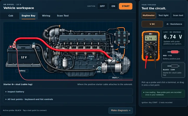
Voltage drop testing asks how much voltage is lost between two points while current flows. That makes it particularly useful for a starter cable or ground path: a connection can look clean and pass a light-current continuity test, yet perform badly under starting load. Use the voltage limits and operating conditions from the vehicle's service information. This guide explains the method without prescribing a universal pass/fail threshold.
Why the load matters
Resistance causes a voltage loss proportional to current. As a teaching example, 0.01 ohm at 200 amps produces a two-volt drop. Those numbers illustrate the relationship; they are not an acceptable starter specification. A meter's continuity function uses a much smaller current and may not reveal the connection's behaviour during cranking.
With no meaningful current, even a poor cable may show almost no drop. If the starter is not drawing current because its control circuit never operates, a zero cable-drop reading does not prove the cable good. Establish the complaint and operating state first. Distinguish a no-crank condition from a slow-crank condition, then use the specified procedure to create an appropriate test load.
Prepare the test and observe battery voltage
Secure the vehicle in the specified park or neutral condition, apply the parking brake and follow starting precautions. Keep hands and leads clear of moving parts. Starter cables carry high current: never bridge a positive terminal to ground with a tool or probe. Use DC volts, black lead in COM and red lead in the voltage socket. Do not use the current socket for a parallel voltage measurement.
Measure battery voltage directly at the identified battery posts while recording the relevant starting condition. A reading only on the clamps can conceal a poor post-to-clamp connection. Record the loaded voltage and symptom together. Battery condition, state of charge, temperature and starter load affect the result, so compare against the correct procedure rather than one unloaded number.
Measure the positive path
For the usual positive-path arrangement, put the red probe on the battery positive post and the black probe on the starter's main supply stud. During the approved loaded test, the display shows the loss between those points. Identify the main stud correctly; a small starter control terminal is a different circuit.
An excessive loss directs attention to the positive path. Divide the path into smaller sections and test across each suspected connection or conductor under the same conditions. For example, compare post-to-clamp, clamp-to-cable and cable-end-to-stud sections when the design allows safe access. A measurement across a connection is different from measuring that connection against ground.
Keep the comparison consistent. Changing the cranking condition or allowing the battery to discharge between tests can change the current and the observed drop. Follow limits on cranking duration and cooldown in service information. If the readings are not repeatable, investigate the test conditions before deciding which component failed.
Measure the return path
The starter also needs a return path to the battery. On a conventional negative-ground example, red on a suitable starter housing test point and black on the battery negative post gives a positive reading for return-path loss under load. Reversing the probes reverses the sign; interpret the magnitude with the specified polarity and procedure.
Use clean, approved contact points and identify any ground straps, junctions or engine-to-chassis connections in the diagram. Divide an excessive return loss into sections just as you did on the positive side. Do not assume that any painted bolt is a reliable reference. The connection from a battery negative clamp to its post can also be part of the fault.
Turn measurements into a diagnosis
Compare battery voltage, positive-path loss and return-path loss. A large loss on one path can explain why less voltage reaches the starter, but the readings do not automatically establish that the starter itself is healthy. If both paths meet their specifications, continue with the applicable control, starter and mechanical checks.
Write down the two probe locations and loaded condition for every result. That simple habit prevents a supply measurement from being mistaken for a drop measurement. Repair the confirmed cause, repeat the affected tests and verify the original complaint is resolved.
DieselBench's No-Crank scenario provides battery, starter, relay and ground test points with a live simulated meter. Practise comparing both paths and proving a repair. Its faults and readings are generic training models, not vehicle specifications. Use current service information for actual testing, acceptable losses and safe starter access.
Put the method into practice
Use the simulated meter on the matching DieselBench practice area. All current training is free; sign in to save progress. If you are new, start with the no-signup guided circuit.
Practise the No-Crank starter scenario